

Does A Inductor Ever Change Magnetic Flux Direction
 A option of low-value inductors | |
| Type | Passive |
|---|---|
| Working principle | Electromagnetic induction |
| Commencement production | Michael Faraday (1831) |
| Electronic symbol | |
| | |
An inductor, besides called a coil, choke, or reactor, is a passive two-terminal electrical component that stores energy in a magnetic field when electric electric current flows through it.[1] An inductor typically consists of an insulated wire wound into a coil.
When the electric current flowing through the coil changes, the time-varying magnetic field induces an electromotive force (east.m.f.) (voltage) in the usher, described by Faraday'south law of induction. According to Lenz's police force, the induced voltage has a polarity (direction) which opposes the change in electric current that created it. Every bit a result, inductors oppose any changes in electric current through them.
An inductor is characterized by its inductance, which is the ratio of the voltage to the rate of change of current. In the International Arrangement of Units (SI), the unit of inductance is the henry (H) named for 19th century American scientist Joseph Henry. In the measurement of magnetic circuits, it is equivalent to weber/ampere. Inductors accept values that typically range from 1µH (10−vi H) to 20H. Many inductors have a magnetic core made of iron or ferrite inside the ringlet, which serves to increase the magnetic field and thus the inductance. Along with capacitors and resistors, inductors are 1 of the three passive linear circuit elements that make up electronic circuits. Inductors are widely used in alternating current (AC) electronic equipment, particularly in radio equipment. They are used to cake AC while assuasive DC to pass; inductors designed for this purpose are chosen chokes. They are likewise used in electronic filters to separate signals of dissimilar frequencies, and in combination with capacitors to brand tuned circuits, used to tune radio and Idiot box receivers.
Description [edit]
An electric current flowing through a conductor generates a magnetic field surrounding it. The magnetic flux linkage generated past a given electric current depends on the geometric shape of the excursion. Their ratio defines the inductance .[2] [3] [4] [5] Thus


- .

The inductance of a circuit depends on the geometry of the current path equally well as the magnetic permeability of nearby materials. An inductor is a component consisting of a wire or other conductor shaped to increase the magnetic flux through the excursion, usually in the shape of a coil or helix, with 2 terminals. Winding the wire into a roll increases the number of times the magnetic flux lines link the circuit, increasing the field and thus the inductance. The more than turns, the college the inductance. The inductance as well depends on the shape of the coil, separation of the turns, and many other factors. By adding a "magnetic core" made of a ferromagnetic material similar fe inside the coil, the magnetizing field from the coil will induce magnetization in the fabric, increasing the magnetic flux. The high permeability of a ferromagnetic core can increase the inductance of a coil by a factor of several thousand over what it would be without it.
Constitutive equation [edit]
Any change in the electric current through an inductor creates a changing flux, inducing a voltage across the inductor. By Faraday's police force of consecration, the voltage induced past whatever change in magnetic flux through the circuit is given by[five]


Reformulating the definition of L higher up, we obtain[5]

It follows, that

for L contained of time, current and magnetic flux linkage.
And so inductance is too a measure of the amount of electromotive force (voltage) generated for a given rate of change of current. For case, an inductor with an inductance of 1 henry produces an EMF of 1 volt when the current through the inductor changes at the charge per unit of one ampere per 2nd. This is unremarkably taken to be the constitutive relation (defining equation) of the inductor.
The dual of the inductor is the capacitor, which stores energy in an electrical field rather than a magnetic field. Its electric current–voltage relation is obtained by exchanging current and voltage in the inductor equations and replacing L with the capacitance C.
Lenz's constabulary [edit]
The polarity (direction) of the induced voltage is given past Lenz's police force, which states that the induced voltage will be such as to oppose the change in current.[6] For example, if the current through an inductor is increasing, the induced voltage will be positive at the current'due south archway point and negative at the exit bespeak, tending to oppose the additional current.[7] [eight] [9] The energy from the external circuit necessary to overcome this potential "hill" is beingness stored in the magnetic field of the inductor. If the current is decreasing, the induced voltage will be negative at the current's archway indicate and positive at the exit point, tending to maintain the electric current. In this case free energy from the magnetic field is existence returned to the circuit.
Energy stored in an inductor [edit]
One intuitive explanation as to why a potential difference is induced on a modify of current in an inductor goes every bit follows:
When there is a modify in current through an inductor there is a alter in the strength of the magnetic field. For example, if the current is increased, the magnetic field increases. This, withal, does not come without a toll. The magnetic field contains potential free energy, and increasing the field force requires more than energy to be stored in the field. This energy comes from the electrical current through the inductor. The increment in the magnetic potential energy of the field is provided past a corresponding drop in the electrical potential energy of the charges flowing through the windings. This appears every bit a voltage drop across the windings as long as the current increases. Once the electric current is no longer increased and is held constant, the energy in the magnetic field is constant and no boosted free energy must be supplied, so the voltage drop across the windings disappears.
Similarly, if the electric current through the inductor decreases, the magnetic field forcefulness decreases, and the free energy in the magnetic field decreases. This free energy is returned to the circuit in the form of an increase in the electrical potential energy of the moving charges, causing a voltage rise across the windings.
Derivation [edit]
The work done per unit of measurement charge on the charges passing the inductor is . The negative sign indicates that the work is done against the emf, and is not washed past the emf. The current is the charge per unit time passing through the inductor. Therefore the rate of piece of work washed by the charges confronting the emf, that is the rate of change of energy of the current, is given by


From the constitutive equation for the inductor, and then


In a ferromagnetic cadre inductor, when the magnetic field approaches the level at which the cadre saturates, the inductance will begin to change, it will be a function of the current . Neglecting losses, the energy stored by an inductor with a current passing through information technology is equal to the amount of work required to institute the current through the inductor.


This is given by: , where is the so-called "differential inductance" and is defined as: . In an air core inductor or a ferromagnetic cadre inductor below saturation, the inductance is constant (and equal to the differential inductance), so the stored energy is


For inductors with magnetic cores, the to a higher place equation is only valid for linear regions of the magnetic flux, at currents below the saturation level of the inductor, where the inductance is approximately constant. Where this is not the case, the integral class must be used with variable.

Voltage step response - brusque and long term limit [edit]
When a voltage step is applied to an inductor, it's short and long-term response are easy to calculate:
Ideal and existent inductors [edit]
The constitutive equation describes the behavior of an ideal inductor with inductance , and without resistance, capacitance, or free energy dissipation. In exercise, inductors exercise not follow this theoretical model; real inductors have a measurable resistance due to the resistance of the wire and energy losses in the core, and parasitic capacitance due to electric potentials betwixt turns of the wire.[ten] [xi]
A existent inductor'south capacitive reactance rises with frequency, and at a sure frequency, the inductor will carry as a resonant excursion. In a higher place this self-resonant frequency, the capacitive reactance is the ascendant role of the inductor'due south impedance. At college frequencies, resistive losses in the windings increment due to the skin result and proximity consequence.
Inductors with ferromagnetic cores feel additional energy losses due to hysteresis and eddy currents in the cadre, which increase with frequency. At high currents, magnetic cadre inductors too show sudden departure from ideal behavior due to nonlinearity caused by magnetic saturation of the core.
Inductors radiate electromagnetic energy into surrounding space and may absorb electromagnetic emissions from other circuits, resulting in potential electromagnetic interference.
An early solid-country electrical switching and amplifying device chosen a saturable reactor exploits saturation of the cadre every bit a means of stopping the inductive transfer of current via the core.
Q factor [edit]
The winding resistance appears as a resistance in series with the inductor; it is referred to as DCR (DC resistance). This resistance dissipates some of the reactive free energy. The quality gene (or Q) of an inductor is the ratio of its inductive reactance to its resistance at a given frequency, and is a measure out of its efficiency. The higher the Q factor of the inductor, the closer information technology approaches the behavior of an ideal inductor. High Q inductors are used with capacitors to brand resonant circuits in radio transmitters and receivers. The college the Q is, the narrower the bandwidth of the resonant circuit.
The Q factor of an inductor is divers as, where L is the inductance, R is the DCR, and the product ωL is the inductive reactance:

Q increases linearly with frequency if Fifty and R are constant. Although they are abiding at depression frequencies, the parameters vary with frequency. For example, peel effect, proximity consequence, and cadre losses increase R with frequency; winding capacitance and variations in permeability with frequency affect L.
At low frequencies and within limits, increasing the number of turns North improves Q because L varies as N 2 while R varies linearly with North. Similarly increasing the radius r of an inductor improves (or increases) Q considering L varies with r two while R varies linearly with r. So loftier Q air core inductors oftentimes have big diameters and many turns. Both of those examples assume the bore of the wire stays the same, so both examples use proportionally more wire. If the total mass of wire is held constant, then there would be no advantage to increasing the number of turns or the radius of the turns because the wire would have to exist proportionally thinner.
Using a high permeability ferromagnetic cadre can greatly increase the inductance for the same corporeality of copper, then the core can besides increment the Q. Cores still likewise introduce losses that increase with frequency. The core textile is chosen for all-time results for the frequency band. High Q inductors must avoid saturation; one way is by using a (physically larger) air cadre inductor. At VHF or college frequencies an air core is likely to exist used. A well designed air core inductor may accept a Q of several hundred.
Applications [edit]

Case of indicate filtering. In this configuration, the inductor blocks AC current, while allowing DC current to pass.
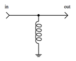
Example of signal filtering. In this configuration, the inductor decouples DC current, while allowing AC current to laissez passer.
Inductors are used extensively in analog circuits and point processing. Applications range from the use of large inductors in power supplies, which in conjunction with filter capacitors remove ripple which is a multiple of the mains frequency (or the switching frequency for switched-manner power supplies) from the direct current output, to the small inductance of the ferrite dewdrop or torus installed around a cable to foreclose radio frequency interference from being transmitted down the wire. Inductors are used every bit the energy storage device in many switched-mode power supplies to produce DC current. The inductor supplies energy to the circuit to keep current flowing during the "off" switching periods and enables topographies where the output voltage is college than the input voltage.
A tuned circuit, consisting of an inductor connected to a capacitor, acts as a resonator for oscillating current. Tuned circuits are widely used in radio frequency equipment such as radio transmitters and receivers, as narrow bandpass filters to select a single frequency from a composite signal, and in electronic oscillators to generate sinusoidal signals.
Two (or more) inductors in proximity that have coupled magnetic flux (common inductance) class a transformer, which is a fundamental component of every electric utility power grid. The efficiency of a transformer may subtract as the frequency increases due to eddy currents in the core textile and peel effect on the windings. The size of the core tin be decreased at college frequencies. For this reason, aircraft use 400 hertz alternating electric current rather than the usual 50 or 60 hertz, assuasive a great saving in weight from the use of smaller transformers.[12] Transformers enable switched-mode power supplies that isolate the output from the input.
Inductors are likewise employed in electrical transmission systems, where they are used to limit switching currents and fault currents. In this field, they are more than unremarkably referred to every bit reactors.
Inductors have parasitic effects which cause them to depart from ideal behavior. They create and suffer from electromagnetic interference (EMI). Their physical size prevents them from being integrated on semiconductor chips. So the use of inductors is failing in modern electronic devices, specially meaty portable devices. Real inductors are increasingly existence replaced by agile circuits such as the gyrator which can synthesize inductance using capacitors.
Inductor construction [edit]

A ferrite core inductor with 2 20 mH windings.

Large l Mvar three-phase iron-core loading inductor at a utility substation
An inductor usually consists of a coil of conducting cloth, typically insulated copper wire, wrapped around a core either of plastic (to create an air-cadre inductor) or of a ferromagnetic (or ferrimagnetic) material; the latter is called an "iron core" inductor. The high permeability of the ferromagnetic core increases the magnetic field and confines it closely to the inductor, thereby increasing the inductance. Low frequency inductors are constructed like transformers, with cores of electrical steel laminated to prevent eddy currents. 'Soft' ferrites are widely used for cores above audio frequencies, since they exercise not cause the large free energy losses at high frequencies that ordinary iron alloys practice. Inductors come up in many shapes. Some inductors take an adjustable core, which enables changing of the inductance. Inductors used to block very high frequencies are sometimes made by stringing a ferrite bead on a wire.
Small inductors can be etched directly onto a printed excursion board by laying out the trace in a spiral pattern. Some such planar inductors utilize a planar core. Small value inductors tin also be built on integrated circuits using the same processes that are used to make interconnects. Aluminium interconnect is typically used, laid out in a spiral coil blueprint. However, the small dimensions limit the inductance, and it is far more common to utilize a excursion called a gyrator that uses a capacitor and active components to behave similarly to an inductor. Regardless of the design, because of the low inductances and low ability dissipation on-die inductors allow, they are currently just commercially used for loftier frequency RF circuits.
Shielded inductors [edit]
Inductors used in power regulation systems, lighting, and other systems that crave depression-noise operating weather, are often partially or fully shielded.[13] [fourteen] In telecommunications circuits employing induction coils and repeating transformers shielding of inductors in close proximity reduces circuit cross-talk.
Types [edit]
Air-core inductor [edit]

These coils illustrate high power high Q construction: unmarried layer winding with turns spaced apart to reduce proximity upshot losses, fabricated of silver-plated wire or tubing to reduce skin consequence losses, supported by narrow insulating strips to reduce dielectric losses
The term air cadre scroll describes an inductor that does not utilise a magnetic cadre made of a ferromagnetic material. The term refers to coils wound on plastic, ceramic, or other nonmagnetic forms, as well equally those that have merely air inside the windings. Air cadre coils take lower inductance than ferromagnetic core coils, simply are often used at high frequencies because they are complimentary from free energy losses chosen core losses that occur in ferromagnetic cores, which increase with frequency. A side effect that can occur in air core coils in which the winding is not rigidly supported on a form is 'microphony': mechanical vibration of the windings tin cause variations in the inductance.
Radio-frequency inductor [edit]
![]()
Collection of RF inductors, showing techniques to reduce losses. The three peak left and the ferrite loopstick or rod antenna,[fifteen] [xvi] [17] [xviii] bottom, accept basket windings.
At high frequencies, specially radio frequencies (RF), inductors have higher resistance and other losses. In addition to causing ability loss, in resonant circuits this can reduce the Q factor of the excursion, broadening the bandwidth. In RF inductors, which are mostly air core types, specialized construction techniques are used to minimize these losses. The losses are due to these effects:
- Peel effect
- The resistance of a wire to high frequency current is higher than its resistance to direct current because of pare effect. Due to induced eddy currents, radio frequency alternating electric current does not penetrate far into the body of a usher merely travels along its surface. For example, at 6 MHz the peel depth of copper wire is about 0.001 inches (25 µm); most of the current is inside this depth of the surface. Therefore, in a solid wire, the interior portion of the wire may carry footling current, effectively increasing its resistance.
- Proximity effect
- Another similar effect that also increases the resistance of the wire at high frequencies is proximity outcome, which occurs in parallel wires that lie close to each other. The individual magnetic field of adjacent turns induces eddy currents in the wire of the coil, which causes the electric current in the conductor to exist concentrated in a thin strip on the side nigh the adjacent wire. Similar skin result, this reduces the effective cross-sectional area of the wire conducting electric current, increasing its resistance.
- Dielectric losses
- The high frequency electric field near the conductors in a tank curlicue tin can cause the motion of polar molecules in nearby insulating materials, dissipating energy every bit heat. So coils used for tuned circuits are often not wound on ringlet forms merely are suspended in air, supported past narrow plastic or ceramic strips.
- Parasitic capacitance
- The capacitance between private wire turns of the coil, called parasitic capacitance, does not cause energy losses but can modify the behavior of the whorl. Each turn of the curlicue is at a slightly different potential, so the electric field between neighboring turns stores charge on the wire, so the coil acts as if it has a capacitor in parallel with it. At a high enough frequency this capacitance can resonate with the inductance of the whorl forming a tuned circuit, causing the coil to go cocky-resonant.
![]()

(left) Spiderweb coil (correct) Adjustable ferrite slug-tuned RF coil with basketweave winding and litz wire
To reduce parasitic capacitance and proximity outcome, high Q RF coils are constructed to avoid having many turns lying close together, parallel to ane another. The windings of RF coils are often express to a unmarried layer, and the turns are spaced apart. To reduce resistance due to skin issue, in loftier-power inductors such equally those used in transmitters the windings are sometimes fabricated of a metal strip or tubing which has a larger surface area, and the surface is argent-plated.
- Basket-weave coils
- To reduce proximity effect and parasitic capacitance, multilayer RF coils are wound in patterns in which successive turns are not parallel but criss-crossed at an angle; these are often called honeycomb or handbasket-weave coils. These are occasionally wound on a vertical insulating supports with dowels or slots, with the wire weaving in and out through the slots.
- Spiderweb coils
- Another construction technique with similar advantages is flat spiral coils. These are ofttimes wound on a flat insulating support with radial spokes or slots, with the wire weaving in and out through the slots; these are called spiderweb coils. The grade has an odd number of slots, so successive turns of the screw lie on opposite sides of the course, increasing separation.
- Litz wire
- To reduce skin consequence losses, some coils are wound with a special type of radio frequency wire called litz wire. Instead of a single solid conductor, litz wire consists of a number of smaller wire strands that deport the current. Unlike ordinary stranded wire, the strands are insulated from each other, to prevent skin effect from forcing the current to the surface, and are twisted or braided together. The twist design ensures that each wire strand spends the same amount of its length on the outside of the wire bundle, and so skin issue distributes the current equally between the strands, resulting in a larger cross-sectional conduction area than an equivalent unmarried wire.
- Axial Inductor
Pocket-sized inductors for depression current and depression power are fabricated in molded cases resembling resistors. These may exist either patently (phenolic) core or ferrite core. An ohmmeter readily distinguishes them from like-sized resistors past showing the low resistance of the inductor.
Ferromagnetic-core inductor [edit]
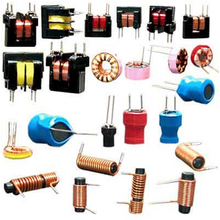
A multifariousness of types of ferrite core inductors and transformers
Ferromagnetic-cadre or fe-cadre inductors use a magnetic cadre made of a ferromagnetic or ferrimagnetic material such as iron or ferrite to increase the inductance. A magnetic core tin increase the inductance of a gyre by a gene of several thou, by increasing the magnetic field due to its higher magnetic permeability. However the magnetic properties of the cadre cloth cause several side effects which change the behavior of the inductor and crave special construction:
- Core losses
- A time-varying current in a ferromagnetic inductor, which causes a time-varying magnetic field in its core, causes free energy losses in the core textile that are prodigal as heat, due to 2 processes:
- Eddy currents
- From Faraday'southward law of consecration, the changing magnetic field can induce circulating loops of electric current in the conductive metal core. The energy in these currents is dissipated as oestrus in the resistance of the core fabric. The amount of energy lost increases with the expanse inside the loop of current.
- Hysteresis
- Changing or reversing the magnetic field in the core also causes losses due to the motion of the tiny magnetic domains it is composed of. The free energy loss is proportional to the expanse of the hysteresis loop in the BH graph of the core material. Materials with depression coercivity accept narrow hysteresis loops and and then low hysteresis losses.
- Saturation
- If the current through a magnetic core scroll is high enough that the core saturates, the inductance will fall and current will ascension dramatically. This is a nonlinear threshold phenomenon and results in baloney of the indicate. For case, audio signals can endure intermodulation baloney in saturated inductors. To forbid this, in linear circuits the current through iron core inductors must exist limited below the saturation level. Some laminated cores have a narrow air gap in them for this purpose, and powdered fe cores take a distributed air gap. This allows higher levels of magnetic flux and thus higher currents through the inductor before information technology saturates.[19]
- Curie signal demagnetization
- If the temperature of a ferromagnetic or ferrimagnetic core rises to a specified level, the magnetic domains dissociate, and the material becomes paramagnetic, no longer able to support magnetic flux. The inductance falls and current rises dramatically, similarly to what happens during saturation. The effect is reversible: When the temperature falls below the Curie indicate, magnetic flux resulting from electric current in the electric circuit will realign the magnetic domains of the core and its magnetic flux volition be restored. The Curie signal of ferromagnetic materials (iron alloys) is quite high; atomic number 26 is highest at 770°C. However, for some ferrimagnetic materials (ceramic iron compounds – ferrites) the Curie point can be close to ambient temperatures (below 100°C).[ citation needed ]
Laminated-cadre inductor [edit]

Low-frequency inductors are often made with laminated cores to prevent boil currents, using construction similar to transformers. The core is fabricated of stacks of sparse steel sheets or laminations oriented parallel to the field, with an insulating coating on the surface. The insulation prevents eddy currents betwixt the sheets, so any remaining currents must exist within the cross sectional area of the individual laminations, reducing the surface area of the loop and thus reducing the energy losses greatly. The laminations are made of depression-conductivity silicon steel to farther reduce eddy current losses.
Ferrite-cadre inductor [edit]
For college frequencies, inductors are made with cores of ferrite. Ferrite is a ceramic ferrimagnetic fabric that is nonconductive, then eddy currents cannot menses within it. The conception of ferrite is xxFe2O4 where xx represents various metals. For inductor cores soft ferrites are used, which take depression coercivity and thus low hysteresis losses.
Powdered-atomic number 26-core inductor [edit]
Some other material is powdered atomic number 26 cemented with a binder.
Toroidal-core inductor [edit]
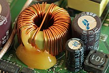
Toroidal inductor in the ability supply of a wireless router
In an inductor wound on a straight rod-shaped cadre, the magnetic field lines emerging from one end of the core must pass through the air to re-enter the cadre at the other terminate. This reduces the field, considering much of the magnetic field path is in air rather than the higher permeability core material and is a source of electromagnetic interference. A higher magnetic field and inductance can be accomplished by forming the core in a closed magnetic circuit. The magnetic field lines form closed loops within the core without leaving the core cloth. The shape oft used is a toroidal or doughnut-shaped ferrite core. Considering of their symmetry, toroidal cores allow a minimum of the magnetic flux to escape outside the core (called leakage flux), so they radiate less electromagnetic interference than other shapes. Toroidal core coils are manufactured of various materials, primarily ferrite, powdered iron and laminated cores.[20]
Variable inductor [edit]


(left) Inductor with a threaded ferrite slug (visible at top) that tin can be turned to motility it into or out of the ringlet, iv.2 cm high. (right) A variometer used in radio receivers in the 1920s

A "roller coil", an adaptable air-cadre RF inductor used in the tuned circuits of radio transmitters. One of the contacts to the scroll is made by the small-scale grooved wheel, which rides on the wire. Turning the shaft rotates the roll, moving the contact wheel upwardly or down the coil, allowing more or fewer turns of the ringlet into the excursion, to alter the inductance.
Probably the well-nigh mutual type of variable inductor today is 1 with a moveable ferrite magnetic core, which can exist slid or screwed in or out of the whorl. Moving the cadre farther into the coil increases the permeability, increasing the magnetic field and the inductance. Many inductors used in radio applications (usually less than 100 MHz) utilize adjustable cores in order to tune such inductors to their desired value, since manufacturing processes have certain tolerances (inaccuracy). Sometimes such cores for frequencies above 100 MHz are fabricated from highly conductive non-magnetic material such as aluminum.[21] They decrease the inductance because the magnetic field must featherbed them.
Air core inductors can utilize sliding contacts or multiple taps to increase or decrease the number of turns included in the circuit, to change the inductance. A type much used in the past merely generally obsolete today has a jump contact that can slide along the bare surface of the windings. The disadvantage of this type is that the contact usually brusk-circuits 1 or more than turns. These turns act like a single-turn short-circuited transformer secondary winding; the large currents induced in them cause power losses.
A type of continuously variable air cadre inductor is the variometer. This consists of 2 coils with the aforementioned number of turns connected in serial, 1 inside the other. The inner coil is mounted on a shaft so its axis can be turned with respect to the outer coil. When the two coils' axes are collinear, with the magnetic fields pointing in the aforementioned management, the fields add and the inductance is maximum. When the inner roll is turned so its axis is at an angle with the outer, the common inductance between them is smaller so the total inductance is less. When the inner whorl is turned 180° and then the coils are collinear with their magnetic fields opposing, the 2 fields cancel each other and the inductance is very small. This type has the advantage that it is continuously variable over a wide range. It is used in antenna tuners and matching circuits to friction match depression frequency transmitters to their antennas.
Another method to control the inductance without any moving parts requires an additional DC electric current bias winding which controls the permeability of an easily saturable core material. See Magnetic amplifier.
Choke [edit]

An MF or HF radio choke for tenths of an ampere, and a ferrite dewdrop VHF asphyxiate for several amperes.
A choke is an inductor designed specifically for blocking loftier-frequency alternating current (Air conditioning) in an electrical circuit, while allowing DC or low-frequency signals to pass. Considering the inductor resistricts or "chokes" the changes in current, this blazon of inductor is called a asphyxiate. Information technology ordinarily consists of a curl of insulated wire wound on a magnetic cadre, although some consist of a donut-shaped "bead" of ferrite cloth strung on a wire. Like other inductors, chokes resist changes in current passing through them increasingly with frequency. The departure between chokes and other inductors is that chokes do not crave the high Q gene construction techniques that are used to reduce the resistance in inductors used in tuned circuits.
Circuit analysis [edit]
The effect of an inductor in a circuit is to oppose changes in current through information technology by developing a voltage across it proportional to the rate of change of the current. An ideal inductor would offering no resistance to a constant straight electric current; notwithstanding, only superconducting inductors have truly zippo electrical resistance.
The relationship between the time-varying voltage v(t) across an inductor with inductance L and the time-varying current i(t) passing through it is described by the differential equation:

When there is a sinusoidal alternating current (Ac) through an inductor, a sinusoidal voltage is induced. The amplitude of the voltage is proportional to the product of the aamplitude (I P) of the current and the frequency (f) of the current.

In this situation, the phase of the current lags that of the voltage by π/2 (90°). For sinusoids, as the voltage beyond the inductor goes to its maximum value, the current goes to nil, and equally the voltage across the inductor goes to zero, the current through it goes to its maximum value.
If an inductor is connected to a straight current source with value I via a resistance R (at to the lowest degree the DCR of the inductor), and then the electric current source is short-circuited, the differential human relationship above shows that the current through the inductor will discharge with an exponential decay:

Reactance [edit]
The ratio of the peak voltage to the superlative current in an inductor energised from an Ac source is called the reactance and is denoted X L.

Thus,

where ω is the angular frequency.
Reactance is measured in ohms merely referred to equally impedance rather than resistance; energy is stored in the magnetic field as current rises and discharged every bit current falls. Inductive reactance is proportional to frequency. At low frequency the reactance falls; at DC, the inductor behaves as a short circuit. As frequency increases the reactance increases and at a sufficiently loftier frequency the reactance approaches that of an open circuit.
Corner frequency [edit]
In filtering applications, with respect to a particular load impedance, an inductor has a corner frequency defined equally:

Laplace circuit analysis (southward-domain) [edit]
When using the Laplace transform in excursion analysis, the impedance of an platonic inductor with no initial current is represented in the s domain by:

where
- is the inductance, and
- is the circuitous frequency.

If the inductor does have initial electric current, it tin can be represented by:
Inductor networks [edit]
Inductors in a parallel configuration each accept the same potential difference (voltage). To notice their full equivalent inductance (50 eq):


The electric current through inductors in series stays the same, but the voltage across each inductor can be different. The sum of the potential differences (voltage) is equal to the full voltage. To find their total inductance:


These unproblematic relationships concord true only when there is no mutual coupling of magnetic fields between private inductors.
Mutual inductance [edit]
Mutual inductance occurs when the magnetic field of an inductor induces a magnetic field in an adjacent inductor. Common induction is the ground of transformer construction.

where Thou is the maximum mutual inductance possible between 2 inductors and Lane and 502 are the 2 inductors. In full general

as only a fraction of cocky flux is linked with the other. This fraction is called "Coefficient of flux linkage (K)" or "Coefficient of coupling".

Inductance formulas [edit]
The tabular array below lists some common simplified formulas for calculating the gauge inductance of several inductor constructions.
| Construction | Formula | Notes |
|---|---|---|
| Cylindrical air-core curlicue[22] |
| Calculation of Nagaoka's coefficient (M) is complicated; normally it must exist looked up from a table.[23] |
| Direct wire conductor[24] | , where:
| Verbal if ω = 0, or if ω = ∞. The term B subtracts rather than adds. |
| (when d² f ≫ ane mm² MHz) (when d² f ≪ 1 mm² MHz)
| Requires ℓ > 100d [27] For relative permeability μ r = 1 (e.g., Cu or Al). | |
| Pocket-size loop or very short coil[28] |
| Conductor μ r should be as shut to i as possible – copper or aluminum rather than a magnetic or paramagnetic metal. |
| Medium or long air-core cylindrical coil[30] [31] |
| Requires cylinder length ℓ > 0.4r: Length must be at least 1⁄five of the diameter. Not applicative to single-loop antennas or very brusk, stubby coils. |
| Multilayer air-core curlicue[32] |
| |
| Flat spiral air-cadre coil[33] [34] [35] |
| |
| Accurate to within 5 percent for d > 0.2r.[36] | |
| Toroidal air-core (circular cantankerous-department)[37] |
| |
| Approximation when d < 0.1D | |
| Toroidal air-core (rectangular cross-section)[36] |
|


![{\displaystyle L={\frac {\mu _{0}}{2\pi }}\ \ell \left[\ln \left({\frac {4\ell }{d}}\right)-1\right]}](https://wikimedia.org/api/rest_v1/media/math/render/svg/179b5909f1eebeb63ead7ec88aa441c758ce1bd2)
![{\displaystyle L={\frac {\mu _{0}}{2\pi }}\ \ell \left[\ln \left({\frac {4\ell }{d}}\right)-{\frac {3}{4}}\right]}](https://wikimedia.org/api/rest_v1/media/math/render/svg/b966d0d02289adc8a86a9430cf195e36c1686175)
![{\displaystyle L\approx {\frac {\mu _{0}}{2\pi }}N^{2}\pi D\left[\ln \left({\frac {D}{d}}\right)+\left(\ln 8-2\right)\right]+{\sqrt {\frac {\mu _{0}}{2\pi }}}\;{\frac {ND}{d}}{\sqrt {\frac {\mu _{\text{r}}}{2f\sigma }}}}](https://wikimedia.org/api/rest_v1/media/math/render/svg/2a78c89a4565971b1731a7baae30cdf4ca361364)


Encounter also [edit]
- Bellini–Tosi management finder (radio goniometer)
- Hanna bend
- Induction coil
- Induction cooking
- Induction loop
- LC circuit
- RLC excursion
- Saturable reactor – a type of adjustable inductor
- Solenoid
- Accumulator (energy)
Notes [edit]
- ^ Nagaoka's coefficient (M) is approximately 1 for a coil which is much longer than its bore and is tightly wound using modest gauge wire (so that it approximates a electric current canvas).
References [edit]
- ^ Alexander, Charles; Sadiku, Matthew. Fundamentals of Electric Circuits (3 ed.). McGraw-Colina. p. 211.
- ^ Singh, Yaduvir (2011). Electro Magnetic Field Theory. Pearson Education India. p. 65. ISBN978-8131760611.
- ^ Wadhwa, C. Fifty. (2005). Electrical Ability Systems. New Historic period International. p. 18. ISBN978-8122417227.
- ^ Pelcovits, Robert A.; Josh Farkas (2007). Barron's AP Physics C. Barron'southward Educational Series. p. 646. ISBN978-0764137105.
- ^ a b c Purcell, Edward M.; David J. Morin (2013). Electricity and Magnetism. Cambridge Univ. Press. p. 364. ISBN978-1107014022.
- ^ Shamos, Morris H. (2012-ten-16). Great Experiments in Physics: Firsthand Accounts from Galileo to Einstein. Courier Corporation. ISBN9780486139623.
- ^ Schmitt, Ron (2002). Electromagnetics Explained: A Handbook for Wireless/ RF, EMC, and Loftier-Speed Electronics. Elsevier. pp. 75–77. ISBN978-0080505237.
- ^ Jaffe, Robert L.; Taylor, Washington (2018). The Physics of Free energy. Cambridge Univ. Press. p. 51. ISBN978-1108547895.
- ^ Lerner, Lawrence S. (1997). Physics for Scientists and Engineers, Vol. 2. Jones and Bartlet Learning. p. 856. ISBN978-0763704605.
- ^ Bowick, Christopher (2011). RF Circuit Pattern, 2nd Ed. Newnes. pp. 7–eight. ISBN978-0080553429.
- ^ Kaiser, Kenneth L. (2004). Electromagnetic Compatibility Handbook. CRC Printing. pp. vi.iv–6.5. ISBN978-0849320873.
- ^ "Aircraft electrical systems". Wonderquest.com. Retrieved 2010-09-24 .
- ^ Ott, Henry W. (2011). Electromagnetic Compatibility Engineering science. John Wiley and Sons. p. 203. ISBN978-1118210659.
- ^ Violette, Norman (2013). Electromagnetic Compatibility Handbook. Springer. pp. 515–516. ISBN978-9401771443.
- ^ "An Unassuming Antenna – The Ferrite Loopstick". Radio Time Traveller. January 23, 2011. Retrieved March 5, 2014.
- ^ Frost, Phil (Dec 23, 2013). "What's an appropriate core textile for a loopstick antenna?". Apprentice Radio beta. Stack Exchange, Inc. Retrieved March v, 2014.
- ^ Poisel, Richard (2011). Antenna Systems and Electronic Warfare Applications. Artech House. p. 280. ISBN978-1608074846.
- ^ Yadava, R. Fifty. (2011). Antenna and Wave Propagation. PHI Learning Pvt. Ltd. p. 261. ISBN978-8120342910.
- ^ "Inductors 101" (PDF). vishay. Retrieved 2010-09-24 .
- ^ "Inductor and Magnetic Product Terminology" (PDF). Vishay Dale. Retrieved 2012-09-24 .
- ^ "page with aluminum cores" (PDF). Coilcraft catalog. Retrieved 10 July 2015.
- ^ a b Nagaoka, Hantaro (1909-05-06). "The Inductance Coefficients of Solenoids" (PDF). Journal of the College of Science, Imperial University, Tokyo, Japan. 27: 18. Retrieved 2011-11-x .
- ^ Kenneth Fifty. Kaiser, Electromagnetic Compatibility Handbook, p. xxx.64, CRC Printing, 2004 ISBN 0849320879.
- ^ Rosa, Edward B. (1908). "The Cocky and Common Inductances of Linear Conductors" (PDF). Bulletin of the Agency of Standards. iv (two): 301–344. doi:10.6028/bulletin.088.
- ^ Rosa 1908, equation (11a), subst. radius ρ = d/2 and cgs units
- ^ Terman 1943, pp. 48–49, convert to natural logarithms and inches to mm.
- ^ Terman (1943, p. 48) states for ℓ < 100 d, include d/twoℓ within the parentheses.
- ^ Burger, O. & Dvorský, Chiliad. (2015). Magnetic Loop Antenna. Ostrava, Czech republic: EDUCA Goggle box o.p.southward.
- ^ Values of up to one⁄3 wavelength are feasible antennas, merely for windings that long, this formula will be inaccurate.
- ^ ARRL Handbook, 66th Ed. American Radio Relay League (1989).
- ^ "Helical coil reckoner". Kaizer Ability Electronics. 2014-07-09. Retrieved 2020-12-29 .
- ^ Wheeler, H.A. (October 1928). "Simple Inductance Formulas for Radio Coils". Proceedings of the Institute of Radio Engineers. 16 (10): 1398. doi:ten.1109/JRPROC.1928.221309. S2CID 51638679.
- ^ For the second formula, Terman (1943, p. 58) which cites to Wheeler 1928.
- ^ "A Magnetic Elevator for Neutral Atoms into a 2D State-dependent Optical Lattice Experiment". Uni-Bonn . Retrieved 2017-08-xv .
- ^ "Screw whorl calculator". Kaizer Power Electronics. 2014-07-10. Retrieved 2020-12-29 .
- ^ a b Terman 1943, p. 58
- ^ Terman 1943, p. 57

- Source
- Terman, Frederick (1943). Radio Engineers' Handbook. McGraw-Hill.
External links [edit]
| | Await up inductor in Wiktionary, the gratis dictionary. |
| | Wikimedia Eatables has media related to Inductors. |
Source: https://en.wikipedia.org/wiki/Inductor
Posted by: truesdalehimat1991.blogspot.com
0 Response to "Does A Inductor Ever Change Magnetic Flux Direction"
Post a Comment